Why hazardous-area LED lights matter in Italian chemical and pharmaceutical facilities
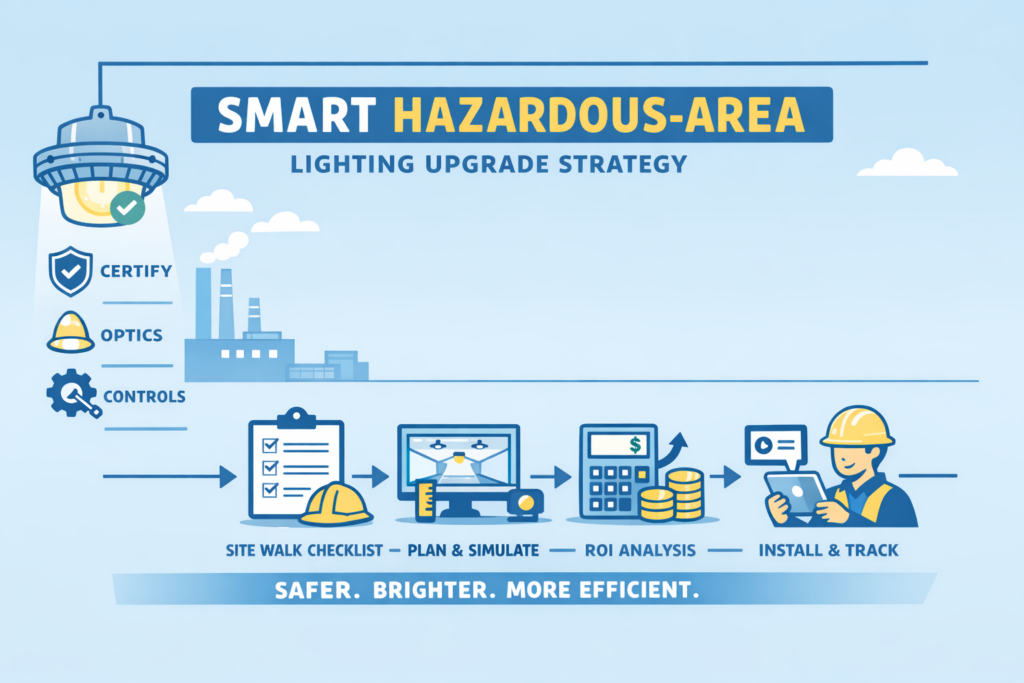
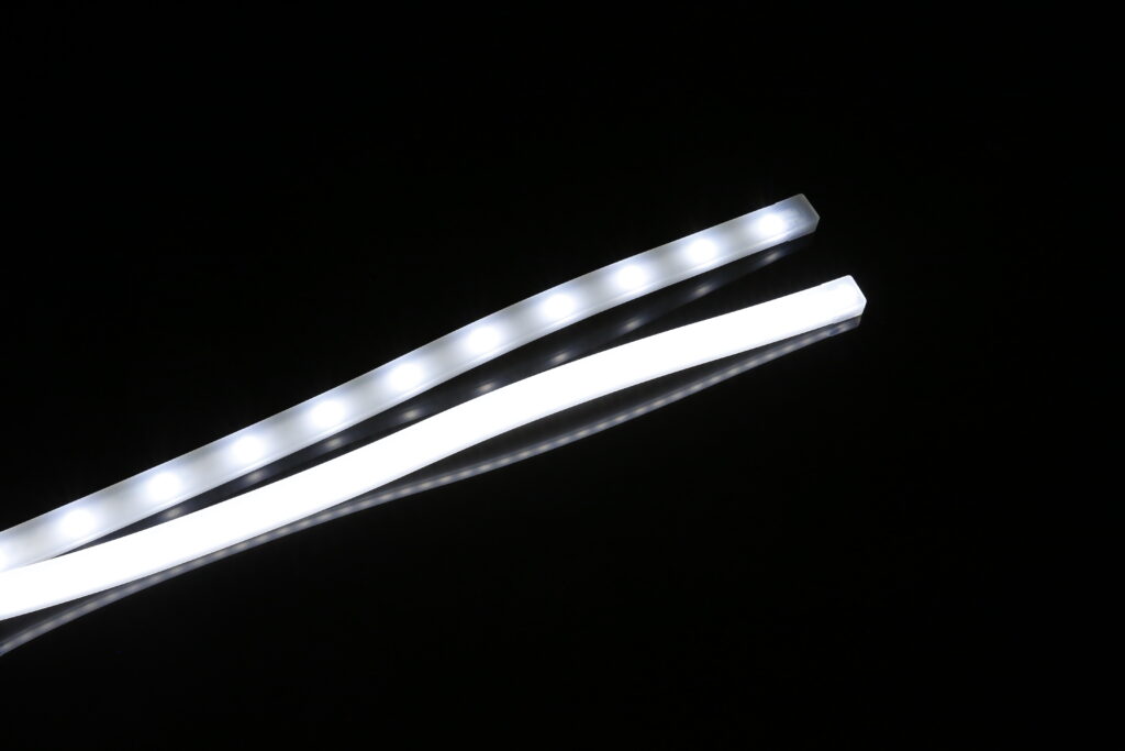
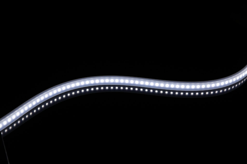
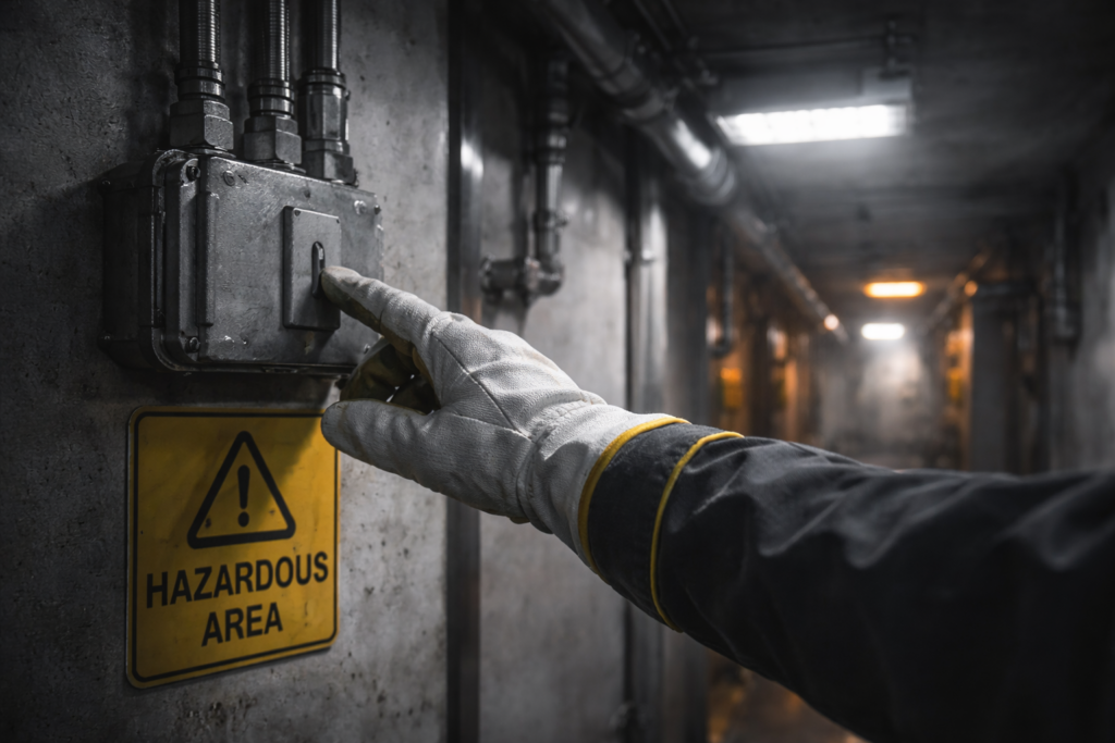
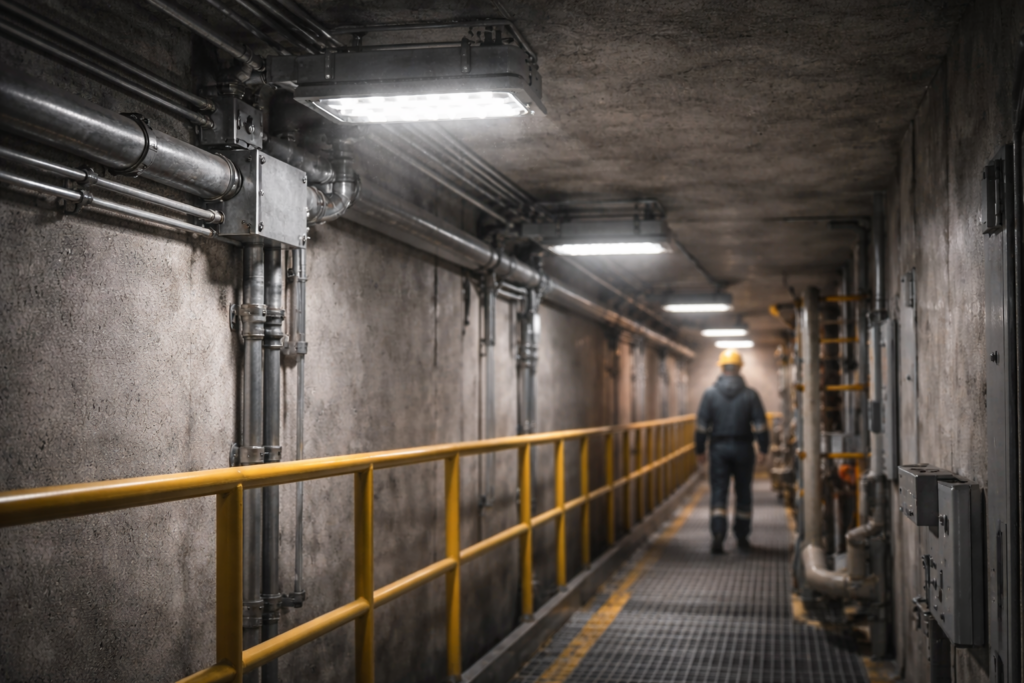
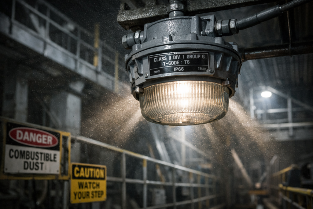
Why hazardous-area LED lights matter in Italian chemical and pharmaceutical facilities Picture a solvent drum filling station near the end of a shift. The operator is checking the liquid level, reading the label, and making sure the coupler is seated properly with no drip at the connection point. It looks routine, maybe even boring. But in a hazardous area, routine is exactly where problems sneak in. That’s the thing people sometimes miss. In Italian chemical processing and pharmaceutical facilities, risk doesn’t always show up as smoke, alarms, or obvious danger. A lot of the time it shows up as poor visibility at the wrong moment. An operator can’t clearly see the meniscus. A label is partly in shadow. A small leak around a fitting goes unnoticed for just a bit too long. None of that sounds dramatic until you remember the environment involves flammable vapors, solvents, dusts, or sensitive processes where one tiny miss can snowball fast. This is why hazardous-area LED lights aren’t just another facility upgrade. They’re part of how the site controls risk, improves inspection, and keeps daily operations steady. And in Italy, where chemical and pharmaceutical production plays a major role in industrial output, lighting choices aren’t trivial. They affect safety, compliance, maintenance, and productivity all at once. For plant engineers and technical teams, that means lighting needs to be evaluated as an operational tool, not just a building service. A fixture that only makes the room look bright from a distance is not doing enough. You need light exactly where people make decisions, where they verify levels, read labels, inspect couplings, and spot residue before it turns into a bigger issue. What makes a light suitable for hazardous areas in Italy? A hazardous-area light has to do more than produce illumination. It has to be designed for environments where explosive atmospheres may occur, and that changes the whole conversation. In Italy, that usually means the lighting strategy has to align with ATEX requirements, area classification, and the actual process risks present in the facility. For chemical processing sites, that can mean solvent vapors around filling lines, decanting stations, blending areas, transfer skids, or storage handling zones. For pharmaceutical facilities, the situation can be more layered. You may have alcohol-based processes, solvent handling, powder transfer, washdown requirements, and stricter expectations around cleanability and inspection quality. So the light has to be safe for the area, but it also has to support the way the room is actually used. A suitable hazardous-area LED luminaire usually needs the right certification, durable seals, solid thermal management, dependable driver performance, and construction materials that can hold up in the real environment. That last part matters more than people think. A fixture may look perfect on a datasheet, then struggle once cleaning chemicals, temperature swings, vibration, or washdown cycles start hitting it week after week. Why do hazardous lighting problems still happen in chemical processing and pharmaceutical plants? Honestly, because the problem is easy to underestimate. A hazardous area doesn’t always look dangerous. A solvent drum fill point can appear clean, controlled, and totally ordinary for most of the day. A pharmaceutical process room can look spotless and highly managed. That surface-level calm makes it easy for lighting design to become generic. The room gets lit, the drawing gets approved, and everyone moves on. Then daily operations begin, and the weak spots show up. The overhead fixture creates glare on stainless steel. The label is readable only from one angle. Hoses cast shadows directly over the connection point. A worker leans in awkwardly just to confirm the liquid line. A fitting looks dry until someone checks it with a handheld torch. That’s not a dramatic failure, but it is a design failure. A lot of hazardous-area lighting problems happen because teams focus on general illumination instead of task visibility. That’s a big difference. General illumination tells you the room isn’t dark. Task visibility tells you the operator can actually do the job safely and correctly. Another reason these issues stick around is that lighting decisions often get pushed late in the project. By then, the layout is already fixed, access is already awkward, and the fixture is expected to solve too many problems at once. That’s when you end up with bulky fittings in the wrong place, shadows at the exact point of work, and a setup that technically exists but doesn’t really support the process. How do hazardous-area LED lights improve drum and IBC fill-point visibility? This is where targeted lighting really earns its keep. Take a solvent drum filling or decanting area. The operator needs to verify the meniscus, check the label, and inspect the coupler for drips or incomplete seating. Those are small visual tasks, but they matter a lot. If the light doesn’t hit those exact points properly, the operator is left working through glare, shadow, or guesswork. A hazardous-area LED strip or narrow-profile linear light can solve that in a much smarter way than a large overhead fixture alone. Instead of trying to flood the whole area with more and more light, it places illumination exactly where it’s needed, at the fill line, the label face, and the fittings. That makes the task easier without crowding the work zone with bulky hardware. And that’s the real advantage of a flexible strip approach in the right application. It lets you bring light close to the meniscus and the coupler area without relying on a distant fixture that throws light everywhere except the place the operator is actually looking. In a solvent drum or IBC fill-point setup, that can mean faster checks, fewer misreads, better label confirmation, and a much easier time spotting residue or small leaks before they become repeat problems. It also improves ergonomics, which people don’t talk about enough. When workers don’t have to lean, twist, or crane their necks to see what’s happening, the task becomes quicker and more consistent. Over time, that adds up. Less hesitation. Less second-checking. Less frustration. And yeah,