What if hazardous-area lights could self-check, slash power use, and make audits painless? Sounds bold—until you map the right standards, optics, and data. Here’s the fast path, plus the choices that matter next.
Key Takeaways
- See where hazardous-area lighting is headed in the next 24 months.
- Learn a simple decision flow to pick optics, certifications, and controls.
- Get a table, a checklist, and a mini playbook to plan upgrades with confidence.
- Run a quick ROI using easy numbers for faster buy-in.
- Walk away with tools and resources to move this week.
Why Hazardous-Area Lighting Is at a Breaking Point
Safety, uptime, and energy. That’s the triangle. Most sites run legacy HID or mixed LED families, patched over years. Heat, vibration, and dust don’t care about purchase orders. Audits come fast, and maintenance logs feel endless. One missed label or wrong optic in a gas zone can turn into downtime—fast. Budgets are tight, yet the target is zero incidents and lower kWh. The old “replace only when it fails” approach drags costs higher and keeps risks hanging around.
Why Hazardous-Area Lighting Is at a Breaking Point
Here’s the shift: modern luminaires bring thermal intelligence, sealed optics, high CRI for inspections, and digital IDs that tie to asset systems. The result is clearer task lighting, less glare, and fewer unplanned lifts. You get predictable maintenance cycles and clean documentation for every fixture. That means safer crews and calmer audits, while energy spend drops. And yes, this includes explosion-proof lighting lines that now talk to gateways or even run diagnostics at the edge.
Start With the Environment, Not the Product Catalog
Every strong lighting plan begins with conditions, not SKUs. Identify the gases, vapors, or dusts present. Confirm the Zone or Division and the required temperature class. Heat is often the silent limiter. LEDs perform best when thermal load stays controlled, and housing design plays a major role in keeping junction temperatures down.
Think of heat like extra weight. As it builds, performance slows and lifespan shortens. Well-designed thermal paths remove that weight, protecting lumen output and extending service life. From there, optics come into focus.
Wide beams suit open production floors. Narrow distributions work better in corridors. Asymmetric optics shine on catwalks, racks, and inspection lanes. Each optic acts like a brush. The wrong one wastes light and adds fixtures. The right one delivers clean coverage with fewer points.
Document key technical terms as you go. ATEX and IECEx classifications, UL844, Class I Division ratings, ingress protection, IK impact resistance, surge protection, and control options all matter later when audits and approvals arrive.
A Practical Decision Framework for Hazardous-Area Lighting Upgrades
Instead of treating every requirement as equal, tier your decisions. This keeps projects focused and defensible
Tiered Decision Framework
- Tier 1: Safety First — Certification match (ATEX/IECEx or UL844), T-rating, surface temperature, IP/IK, corrosion resistance.
- Tier 2: Visual Clarity — Beam pattern, glare limits, CRI for inspection tasks, emergency/battery needs.
- Tier 3: Efficiency & Control — Efficacy (lm/W), dimming, occupancy/daylight sensors, network choice (wired vs. wireless mesh).
- Tier 4: Lifecycle & Ops — L70 hours, driver replaceability, mounting flexibility, spares strategy, digital asset tags.
Planning Table
| Step | What to Do | Tool | Time | Output |
|---|---|---|---|---|
| 1 | Map Zones/Divisions & T-codes | Site drawings + last audit | 1–2 hrs | Risk-based area list |
| 2 | Capture Heights & Tasks | Laser measure, camera | 1 hr | Mount heights + task notes |
| 3 | Pick Optics per Area | Photometric sim | 2–4 hrs | Layout + fixture counts |
| 4 | Select Controls Tier | Controls matrix | 1 hr | Sensor/network plan |
| 5 | Verify Cert & Materials | Spec sheets | 30–60 min | Compliant shortlist |
| 6 | Run ROI & Power | kWh calc sheet | 30–60 min | Payback estimate |
| 7 | Create Asset IDs | CMMS template | 30 min | Maintenance plan |
10-Step Hazardous-Area Lighting Site-Walk Checklist
- Confirm Zone/Division and gas/dust group.
- Note ambient max temp; check hot spots near process lines.
- Measure mounting height and spacing.
- Record current wattage per fixture family.
- Photograph label plates and cable entries.
- Identify glare issues or shadow pockets.
- Flag emergency egress needs and test intervals.
- Decide sensor use: occupancy, daylight, or none.
- Choose network (none, local, or plant-wide).
- Assign fixture IDs that match CMMS fields.
With this framework and checklist, choices turn into a staged rollout—so action becomes the obvious next move.
ROI Calculation for Hazardous-Area LED Lighting Upgrades
Week 1 — Scope & Data
- Pull last compliance report; list red/yellow items.
- Walk one pilot area; run the 10-step checklist.
- Build the planning table; shortlist two fixture families.
Week 2 — Design & Sim
- Run photometric layouts for the pilot.
- Choose optics and mounts; confirm glare limits.
- Lock controls tier (no controls, local sensors, or mesh).
Week 3 — ROI & Buy-In
- Price hardware + lifts; add install hours.
- Model kWh savings and maintenance cuts.
- Draft a one-page brief with risks, mitigations, and payback.
Week 4 — Install & Document
- Install pilot row; measure lux at tasks.
- Tag every unit in CMMS with spec + warranty.
- Schedule 30/60/90-day checks.
Worked Example (Numbers You Can Swap)
- Current: 60 HID fixtures @ 200 W = 12,000 W.
- New LED: 60 @ 90 W = 5,400 W.
- Savings: 6,600 W. Run time: 4,000 hrs/yr → 26,400 kWh saved.
- Energy cost: $0.12/kWh → $3,168/yr saved.
- Maintenance: $45/fixture/year avoided → $2,700/yr saved.
- Total annual benefit ≈ $5,868. If project cost is $24,000, simple payback ≈ 4.1 years, faster with incentives.
Tools, Prompts, Templates
- Photometrics: Vendor software or open IES file viewers.
- CMMS Template: Columns—Fixture ID, Area, Cert, Watt, Optic, Mount, Install Date, Warranty End, Test Date.
- Prompt for audit notes: “Summarize hazards, T-code, optic needs, and sensor choice for Area X in 5 bullets. Include risks and mitigations.”
Lock down these steps, and the pilot becomes a blueprint for broader rollouts—including explosion-proof lighting refreshes in adjacent areas.
Conclusion
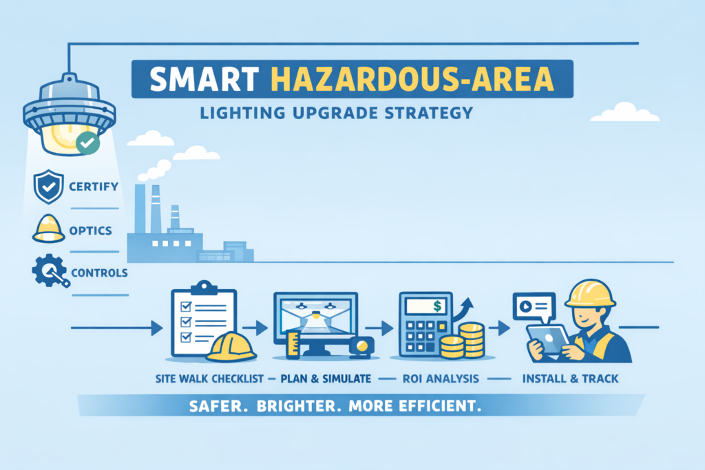
Smarter hazardous-area lighting delivers safer sites, sharper visibility, and lower operating costs. Legacy systems built on heat, guesswork optics, and scattered documentation drain time and trust. The modern approach is simpler. Certify first. Match optics to tasks. Add only the controls you need. Track every fixture like a critical asset.
When upgrades follow a clear framework and roll out in short sprints, audits calm down, crews work with confidence, and energy use drops without disrupting production. Explosion-proof lighting doesn’t have to feel specialized or fragile. Done right, it becomes part of the infrastructure, reliable, efficient, and built in from day one.